Complete Service Repair Manual for Liebherr D934, D936 Diesel Engine.
This manual contains high quality images, specs and Schematics, actual real photo illustrations, circuit diagrams and instructions to help you to operate, diagnostic, maintenance, troubleshoot, and repair your Liebherr D934, D936 Diesel Engine. This document is printable, without restrictions, contains searchable text, bookmarks, crosslinks for easy navigation.
Contents:
1. Product description
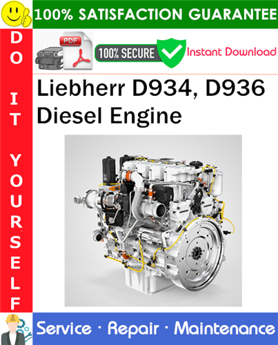
1.1. Illustration of engine 936L
1.2. Technical description
1.3. Special equipment for diesel engine
1.4. Engine classification, engine identification plates, engine number
1.5. Technical data, adjustment values and test values
1.6. Tightening specifications
1.7. Screw tightening values
2. Description of basic engine
2.1. Engine
2.2. Crankcase breather
3. Cylinder head
3.1. Description of cylinder head
3.2. Cylinder head and cylinder head gasket (diagram)
3.3. Replacing the cylinder head gasket
3.4. Carrying out a compression test
4. Lube oil circuit
4.1. Lube oil circuit diagram
4.2. Lube oil pump
4.3. Oil filter
4.4. Oil cooler
4.5. Leakages in the oil cooler
4.6. Oil sump
4.7. Causes of oil pressure problems
4.8. Fuel in thr oil
5. Water circuit
5.1. Diagram of the water circuit
5.2. Cooling water – thermostat
5.3. Cooling water pump
5.4. Dismantling the coolant water pump
5.5. Cooling water in the fuel
6. Suction side
6.1. Exhaust turbocharger
6.3. Heater flange
7. Exhaust side
7.1. iAGR
7.2. eAGR
7.3. Engine brake
7.4. Description of the auxiliary brake system (ZBS)
8. Description of the electronic injection system
8.2. Engine control unit with schematic connection
8.3. Diagnostic description
8.4. Diagnosis and service
8.5. Connection diagram of the sensors
8.6. Sensors
8.7. Electrical system
8.8 Configuration of pump-/nozzle units (PLD-ENGINES ONLY)
9. Description of the mechanical injection system
9.1. Functional description
9.2. Low-pressure circuit
9.3. Checking the low-presure circuit
9.4. Fuel pump ZP 18.5
9.5. Fuel filtering
9.6. Fuel lines
9.7. Draining the upper fuel duct
9.8. Draining the lower fuel duct
9.9. Diagram of pump/nozzle unit with injection nozzle
9.10. Installing and dismantling the pump element (UP 20) with roller tappet
9.11. Bleeding the fuel system
9.12. Diagram of the injection nozzle and pressure pipe tube
9.13. Checking the injection nozzle
9.14. Oil in the fuel system
10. Description of accessories
10.1. Diagram of auxiliary drives
10.2. Air compressor
10.3. Drive for generator and air-conditioning compressor
10.4. Checking the condition of the ribbed V-belt
11. Electrical system
11.1. Starter
11.2. Checking the starter
11.3. Checking the alternator
11.4. Heater flange
12. Maintenance
12.1. Maintenance chart
12.2. Setting the valves
12.3. Setting the valves for the engine auxiliary brake system (ZBS)
13. Fuels
14. Mechanical fault list
15. Electronic fault list
16. Description of level – 1 Parameters and measuring points
————–
File Format: PDF
Requirement: Adobe Reader
Total Pages: 179
Language: English
Compatibility: All Windows Version / Mac and Linux OS, Android
This manual can be used by anyone from a first time owner/amateur to a professional technician. Even the most novice mechanic can also easily follow the step-by-step guides which are made simple by the illustrations and drawings. Keep this manual handy and use it often. Performing routine, preventive maintenance will save you time & money by helping to prevent premature failure and unnecessary repairs.
Download immediately! NO waiting! You will have instant access to your download! No shipping fee, No waiting nervously for the postal delivery, you can start doing your repairs right away!
Customer Satisfaction Guaranteed.